Control and Trajectory Generation of a Quadcopter
This project, as part of my Robot Mobility course at CMU, emphasized the generation of time-parameterized piecewise continuous trajectories and feedback control design to enable an aerial robot (in simulation) to fly along a pre-defined path.
The project sought to:- Develop a basic state machine to facilitate simulation that enables the robot to takeoff, hover, track a trajectory, and land
- Introduce time-parameterized trajectories given fixed initial and final endpoint constraints and bounded velocity and acceleration
- Extend the formulation to include piecewise continuous trajectories with fixed initial and final endpoint constraints
- Evaluate tracking performance given different levels of flight performance and trajectory design
I implemented a number of scenarios of the quadcopter’s movements, and for each of them, tuned the PD gains to minize the error between the desired and actual position. In the sections that follow, different mobile states of the quadcopter are presented along with plots that indicate the margin of error between the desired and the actual states.
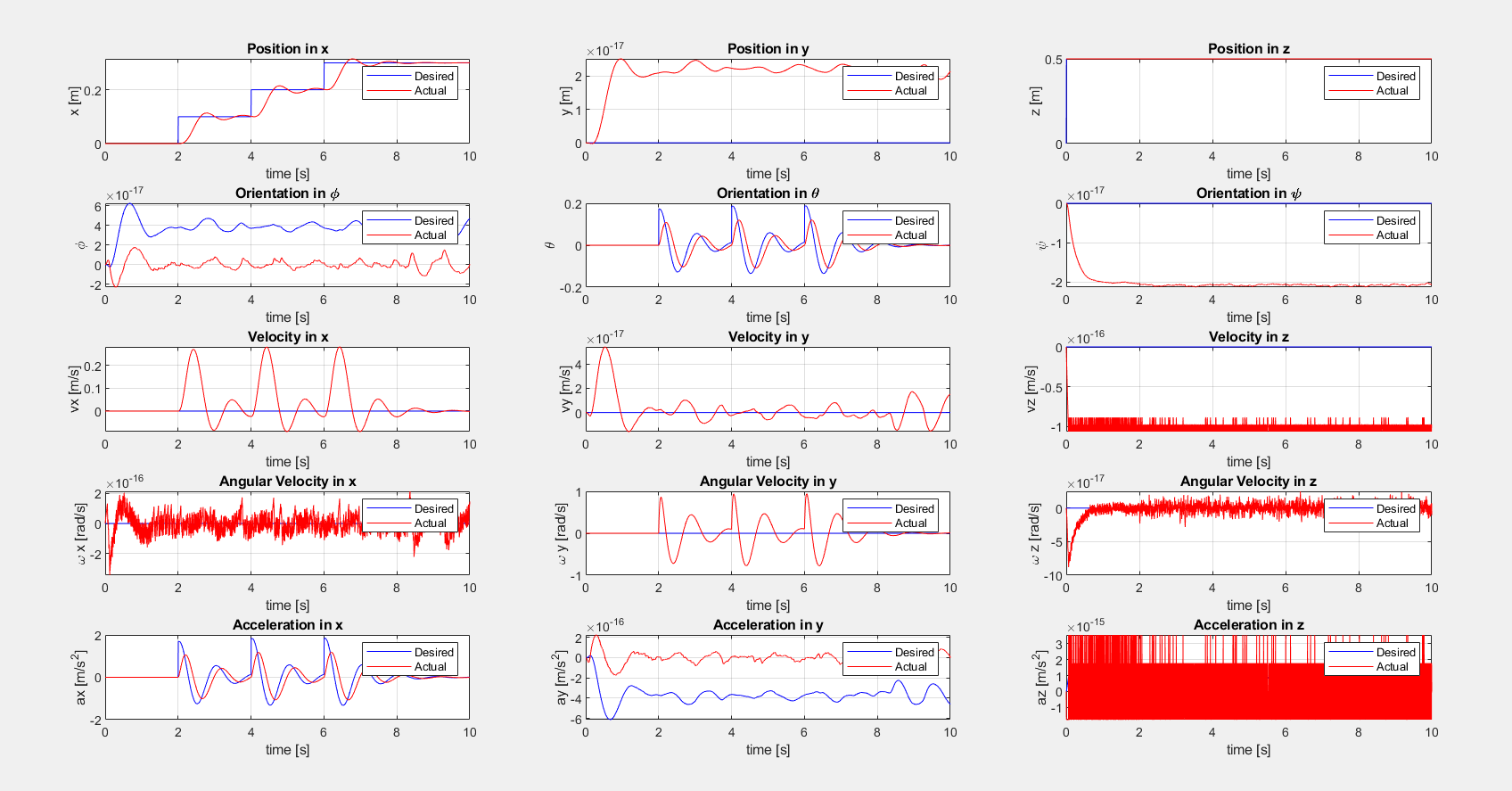
Using a linearized feedback control policy, I implemented a Proportional Derivative feedback controller to enable the robot to hover at a desired location (e.g., z = 0.5 m).
The plot of the desired vs. actual state of the quadcopter hovering is shown below:
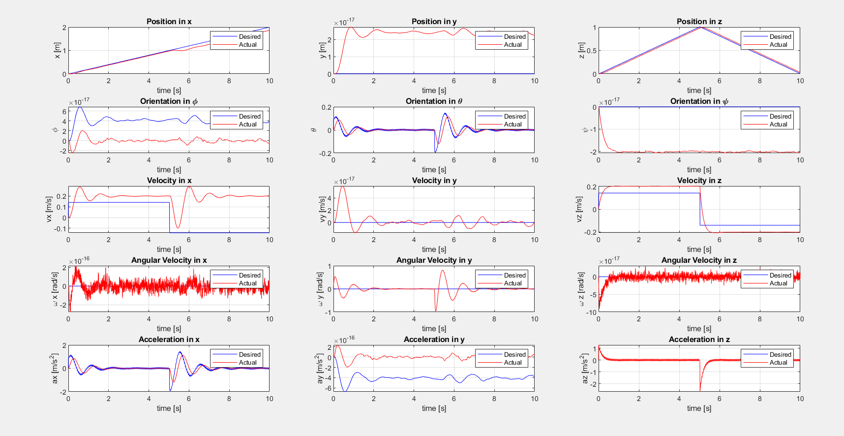
I developed a PD line tracking controller to enable the robot to take-off from a starting location, go to a fixed height of 1.0 m, and return to the ground. The plot of the desired vs. actual state of the quadcopter line-tracking is shown below:
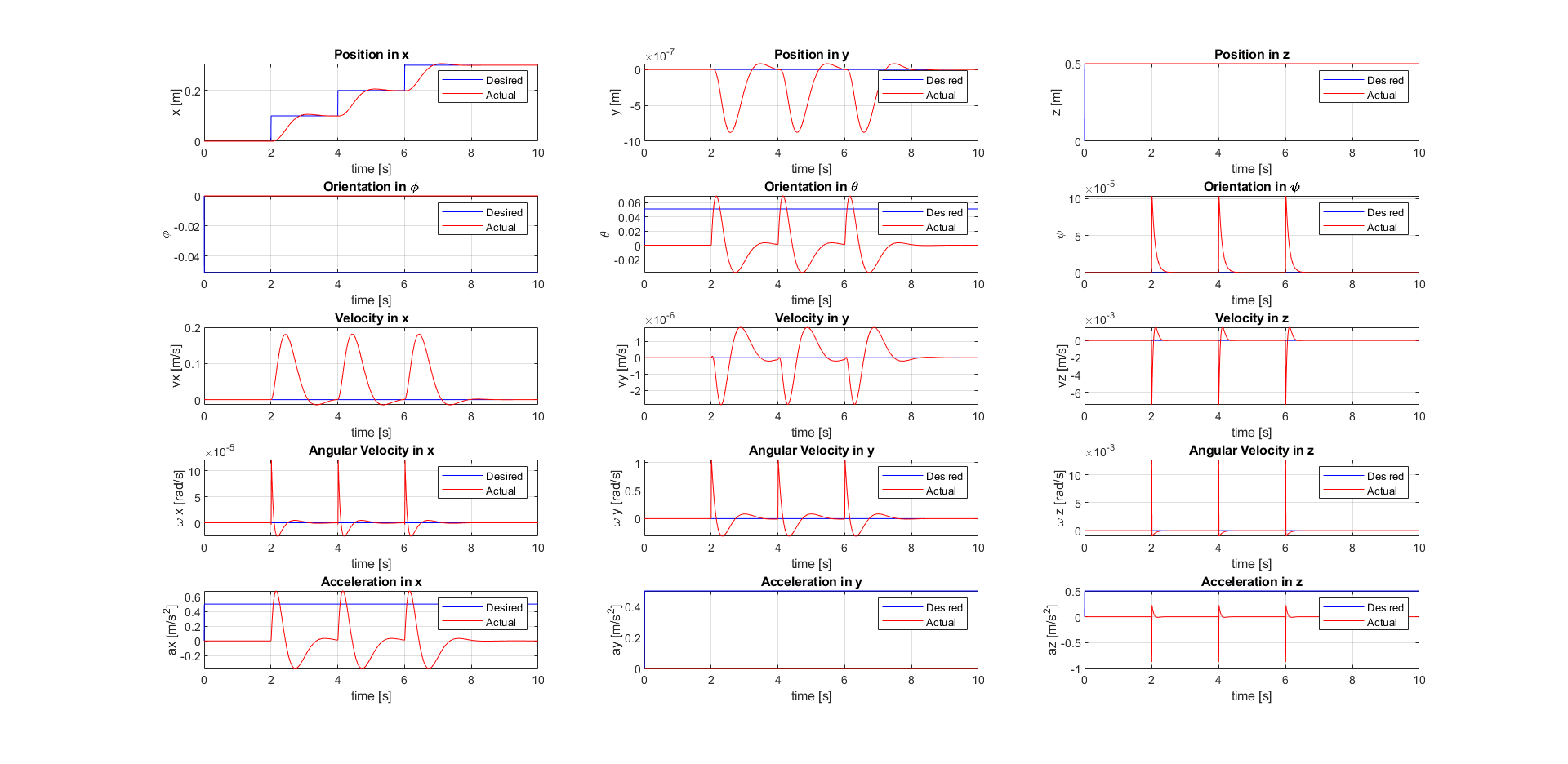
Additionally, I implemented the hover and line tracking case using an LQR-based feedback controller and compared the performance with the PD controller.
The plot of the desired vs. actual state of the quadcopter (LQR-based feedback control) hovering is shown below:
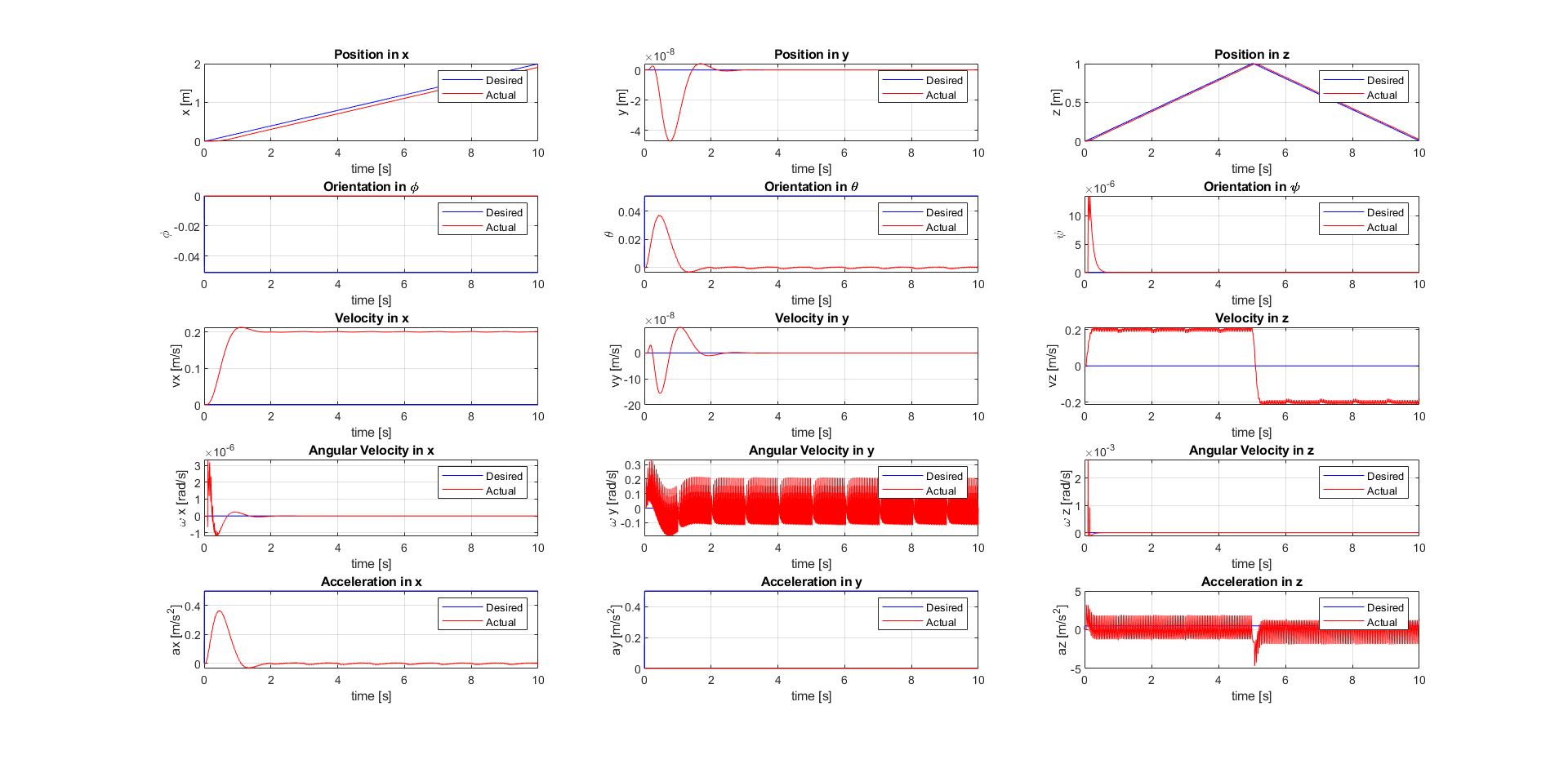
The plot of the desired vs. actual state of the quadcopter (LQR-based feedback control) line-tracking is shown below:
Finally, I defined a piecewise continuous trajectory consisting of four waypoints: [0, 0, 1, 0], [2, 1, 1, 0], [0, 2, 1, 0], [-2, 1, 1, 0] (position, heading). To do so, I generated a trajectory that visits the four waypoints (returning to the first; forming an ellipse) with an initial velocity of zero and an end velocity of 1 m/s at the first waypoint. The robot will start at rest, track the elliptical trajectory, and arrive at the starting location at a non- zero velocity (1 m/s).
The plot of the desired elliptal trajectory (left) and the actual trajectory (right) obtained is shown below:
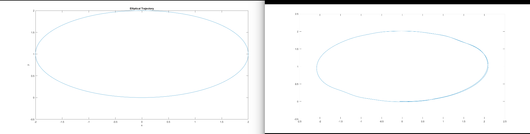 The robot is able to follow the desired trajectory very closely, with minor deviations when it recovers from sharper turns.